- ZIMO Home
- Sound Design
- ZCS
- ZIMO GURU (FAQ)
- Links zu Partner Websites
Command stations and controllers from the "old" Systems (MX1, MX1HS, MX1EC, MX31, MX31FU, MX31ZL) are no longer available!
| The "old" ZIMO System |
.
|
Standard and High, |
Economy |
Controller, |
.More Info - Click on the underlined Product Family (MX1, MX31, ...) ! |
||||
|
Radio Base Module |
Reverse Loop Modules |
Accessory modules |
Track section modules |
Cables and connections |
|||
|
MX1
MX1
Command Station, |
 Technical Information: |
|||||||||||||||||||||||||
|
|
manual for MX1, MX1HS, MX1EC |
|||||||||||||||||||||||||
|
Power
supply by external transformer (MX1HS: 2 Transformer) Stabilized track voltage Max. track current of MX1, output "SCHIENE 1" (Track 1) Max. track current of MX1HS, output "SCHIENE 1", "SCHIENE 2" (Track 1, Track 2) Max. current on programming track (Output "PROG" at MX1) FLASH EPROM / RAM memory Lithium battery for data retainment in RAM Dimensions Weight |
24
- 28 V, min. 150 VA,
e.g.TRAFO25 |
|||||||||||||||||||||||||
|
The
command station, the heart of the ZIMO system, generates stabilized power
to the track, a standardized DCC signal as well as the MOTOROLA format.
Being the CAN bus central unit, it also processes data from the cabs connected
(loco speed and functions, programming procedures etc.) as well as from
a possibly hooked up computer;
It also manages
and controls other ZIMO products, such as accessory and track section modules.
The
track voltage can be adjusted between 12 and 24 Volts to accommodate all
scales and provide optimum conditions for any kind of operation. The high
output current of 8 Amps is enough to power 10 or more HO trains or 5 or
more large scale engines simultaneously. ZIMO's high output MX1HS delivers
even more power with 2x8 Amps for two separate layout sections or, used
in parallel, for one large section.
However, ZIMO's command stations are more than simple high powered digital central units: the big difference to command stations of other DCC systems becomes apparent when looking at the informative display showing voltage and amperage to each track outlet and the status of the CAN bus, it's 8 inputs for automated shuttle train operations and for future expansions ("automatic operations"), the software development possibilities in directions of operational control and train surveillance techniques (block control at first).
|
||||||||||||||||||||||||||
|
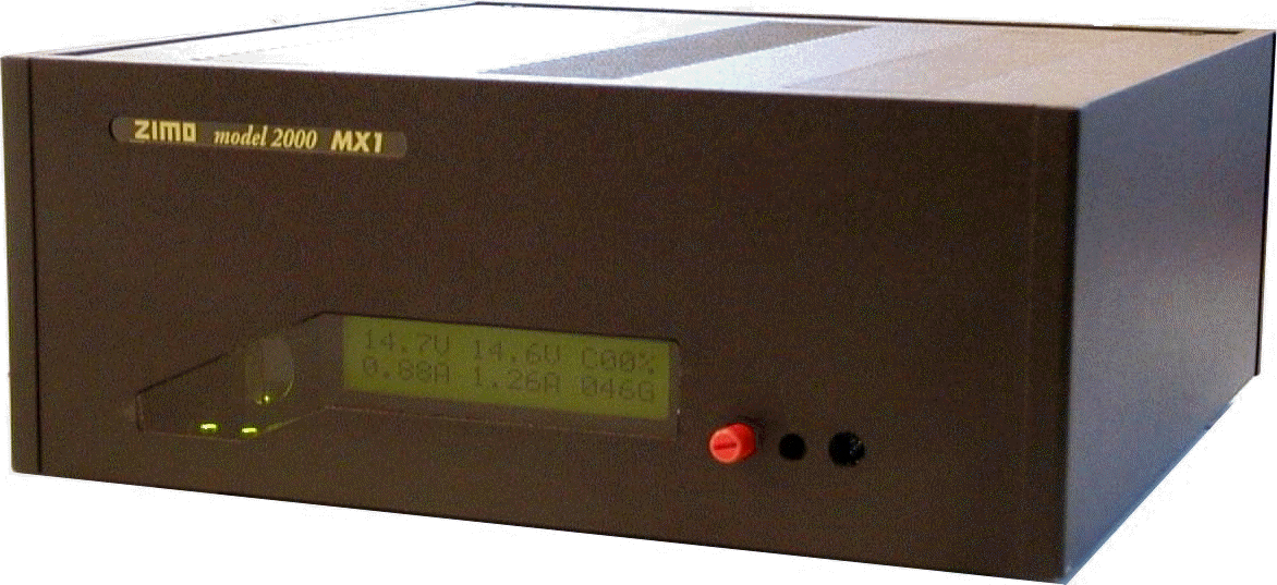
Front view including the MX1 (MX1HS) display:
|
||||||||||||||||||||||||||
Back view of the MX1 (MX1HS)
Configuration Variables of the MX1 (MX1HS): Similar to configuration variables in decoders, general system settings can be configured and certain sequences and functions defined; access to the command station CV's is possible with any cab connected. The RS 232 Interface does several tasks:
The Starter Sets: The
command station MX1 (or MX1HS) is usually obtained as part of a ZIMO starter
set. Additionally, a cab, one or two decoders for the selected scale, the
necessary cable and connectors and a ZIMO manual (which not only contains
the information of the starter set but of all ZIMO components) is part
of a starter set. NOTE: The necessary transformer is not included; TRAFO25
is recommended by ZIMO, but any other transformer can be used (ca. 24V,
min 150VA).
|
 |
|||||||||||||||||||||||||
|
CV # 5, 6
Reduction
of the max. allowable current to the track (0,1 A - 8 A) CV # 7, 8 Power off time during short circuit (adjustable from 0,002 to 0,5 sec) CV # 9, 10 Voltmeter calibration CV # 11, 13, 14 Modification of timing and bit sequence, DCC signal (not for normal use) CV # 11 Bit rate at the RS 232 interface (1200 - 38400 bit/s) CV # 19 Pseudo address to control one analog engine CV # 20, 21 Automatic stop time between change of directions. CV # 22 Time interval of turnout operations in a switching route (0,01 to 4 sec) CV # 25, 26 Zeroing of Amp. meter CV # 27 General selection between "8-Function" and "12-Function” mode. CV # 31 - 38 Assignment of auxiliary inputs for shuttle trains, emergency stop, switching route activation, release of programming protection. CV # 41 - 56 Stop time in a automated shuttle train operation. CV # 57 - 64 Enter switching routes for automatic activation. CV # 81 - 84 Steps to improve data transmission. CV # 93, 94 current tresholds for programming (better results in programming process) CV # 95, 96 wait states and reset packages for programming CV # 100, 101 special CV for ABA's (operating schedules) from CV # 110 special CV for ARA's (automated routing schemes) |
||||||||||||||||||||||||||
|
Order Information
| ||||||||||||||||||||||||||
Last Update: 2010-09-30


