


|
FUNCTION |
MX671/R/N 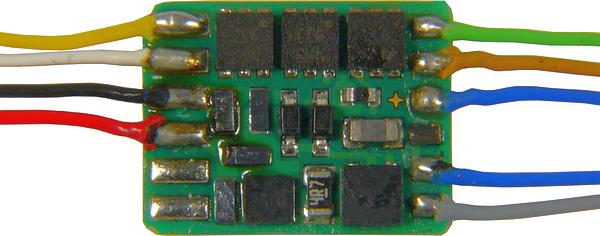 MX671 /R (top)  MX671 /R (bottom)  MX671N (NEM-651dir, top)  MX671N (NEM-651dir, bottom)  |

MX675V MX675V (top)  MX675V (bottom)  |
 MX676VD  MX676VD (top)  MX676VD (bottom)  |
MX685P16 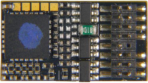 MX685P16 (top)  MX685P16 (bottom)  MX685P16 (persp)  MX685 (top) 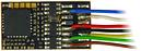 MX685 (persp) 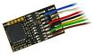 |

|
MX689N18 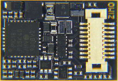 MX689N18 (top)  MX689N18 (bottom)  MX689N18 (persp)  |

FS850  FS850P22 (top)  FS850P22 (persp)  FS850, -R (top)  FS850 (bottom)  FS850, -R (persp)  |

FS890N18  FS890N18 (top)  FS890N18 (persp)  FS890N18 (bottom)  |
||||||||||||||||
|
DECODER FAMILIES |
MX671 MX671R, MX671N |
MX675V
|
MX676VD ZIMO / RailCom Std |
MX685P16 MX685, MX685R |
MX686D
|
MX689N18 |
FS850P22 FS850, FS850R |
FS890N18
|
||||||||||||||||
| Dimensions (mm) | 10,5 x 8 x 2,2 | 25 x 15 x 4 | 26 x 15 x 3.5 | 20 x 11 x 3.5 | 20.5 x 15.5 x 3.5 | 14 x 9.5 x 2.1 | 21 x 15 x 3.6 | 13.6 x 9.3 x 3.1 | ||||||||||||||||
|
The dimensions of decoders with standardized interfaces (PluX, MTC, NEM-651, Next18) correspond to the corresponding standards by VHDM and NMRA or are smaller. In case of the wired decoders, which are protected by a shrinking tube, the indicated dimensions are WITHOUT this tube, because it can be taken off, if there is not enough space. |
||||||||||||||||||||||||
| Operating modes | DCC MM AC DC | DCC mfx MM AC DC | DCC MM DC | |||||||||||||||||||||
|
ZIMO decoders and system devices are multi-protocol capable and support various digital and analogue operating modes. The line above indicates this for the respective decoder.
NOTE: The Systrix (SX) digital system is not supported by ZIMO components. |
||||||||||||||||||||||||
| Connections | 9 wires, with NEM-652, or NEM-651(pins) |
10 wires | 21MTC | PluX-16 / 7 wires / " with NEM-652 |
21MTC | Next18 | PluX-22 / 11 wires / " with NEM-652 |
Next18 | ||||||||||||||||
| Continuous Current (total) | 0.7 A | 1.8 A | 1.8 A | 1 A | 1.2 A | 0.7 A | 1.2 A | 0,7 A | ||||||||||||||||
|
The "continuous current" indicates the maximum output rate of the decoder (total), whereby average surrounding conditions are assumed. What limits the continuous current is the heat development; the integrated temperature sensor turns off the consumers when the PCB reaches about 100°C. Displaying overload (= overcurrent): the decoder quickly flashes the headlights (about 5 Hz= 5 times per second) |
||||||||||||||||||||||||
| Function Outputs | 6 | 12 | 10 / 6 | 8 | 8 | 4 | 10 | 6 | ||||||||||||||||
|
ZIMO decoders have different types of outputs. They vary between the families in number and resilience:
|
||||||||||||||||||||||||
| Current limiter Fu. Out. | 0.85 A | 1.2 A | 1.2 A | 1.2 A | 1.2 A | 0.5 A | 0.8 A | 0,5 A | ||||||||||||||||
For reasons of limited space, the output current of the function outputs is presented in total (all outputs together or in groups). The individual FO is strong enough, though, to cope with all the current, if needed. The specified value should be regarded as the maximum value determined by the overcurrent cut-off. The continuously deliverable current is also influenced by other components and variables such as heat generation and may therefore be lower. The continuous current, total specified above corresponds approximately to this value. In case of overcurrent, the output is not turned off immediately, but after a time in tenths of a second or milliseconds, depending on the amount exceeding the defined threshold. This, inter alia, makes a cold start of light bulbs possible. In case this is not enough, the function "soft start" was developed. |
||||||||||||||||||||||||
| Logic Level Outputs | - | 2, alt. to SUSI | 2 / 5 (2 alt. to SUSI | 2 (alt. to SUSI) | 4 (2 alt. to SUSI) | 4 (2 alt. to SUSI) | 2 (alt. to SUSI), 1 (alt. to LL-IN) |
2, alt. zu SUSI | ||||||||||||||||
"Logic level" (also called "unamplified") outputs provide a voltage level (0V for off, 5V for on) via an internal 10K resistor on an output (i.e. max. 5mA output current), which can be used via an external amplifier. This is usually done by the user, but the M4000Z by ZIMO is also useful; see instruction manual of the decoders. WARNING: "logic level" outputs are NOT active by default, because they use the same contacts as the SUSI-interface (Data & Clock) and as the servo control wires. The user defines, how the shared contacts are used, by setting: CV #124: Bit 7 = 0 -> SUSI Bit 7 = 1 -> Logic Level and CVs #181, #182 (if those are set, the shared contacts are used as servo control wires). The MTC decoder MX676VD can be switched via CV #8 between the ZIMO convention with 10 Fu outputs and the RailCommunity standard with 6 Fu outputs. Conversely, 3 of the 4 outputs become logic level outputs. For details, see operating instructions. |
||||||||||||||||||||||||
| Switch Inputs for cam sensors, Reed switches, i.a. |
- | - | - | - | - | - | 1 (logic level), 2 (alt. to SUSI) |
- | ||||||||||||||||
Switch inputs are used to connect cam sensors directly (to play back chuff sounds synchronously to the axles) or sensors for position dependent sound functions, e.g. warning whistles before a level crossing. Note: The logic-level outputs (see above) can also be used as switch inputs, if needed and the software supports functions with switch inputs (e.g. position dependent lighting effects or loco controlled commuting. This is also valid for non-sound decoders. |
||||||||||||||||||||||||
| Servo Outputs | - | 2, alt. to SUSI | 2, alt. to SUSI | 2, alt. to SUSI | 2, alt. to SUSI | 2 | 2 (alt. to SUSI) 1 (altern. to IN1) |
2, alt. to SUSI | ||||||||||||||||
|
Outputs for servo control wires; with these, standard servos (Graupner, Robbe, etc.) can be controlled, whereby different operating modes as well as end positions, cycle times, etc. can be defined in CVs #161 to #182. Decoders with a 5V low voltage output (MX687W) also provide the operating voltage for the servos. The servo outputs use the same outputs as SUSI (Clock & Data) and are activated with CVs #181, #182; SUSI is then deactivated. |
||||||||||||||||||||||||
| SUSI | - | yes | yes | yes | yes | yes | yes | yes | ||||||||||||||||
The "SUSI" interface originally was designed, because it was difficult to place sound production in the decoder (regarding space and processor performance), and therefore individual sound modules were created which were controlled via SUSI data lines (Clock and Data) by the decoder. Further function outputs could also be realized that way. Those additional modules are partly still on the market, although the solution technically is not up-to-date anymore and related to functional limitations. Most of the ZIMO decoders have "SUSI" connections, because these lines feature a fast transmission protocol for the communication between train (locomotive decoder) and attached cars (function decoders) via conductive couplings. Another use of the "SUSI" interface would be the connection to environmental sensors (tilt, lateral acceleration, GPS, ...) and train radio modules or balise readers in the vehicle. Last, but not least, it made more function outputs possible (see above). |
||||||||||||||||||||||||
| Direct Energy Storage | yes (35 V) | yes (16 V) | yes (16 V) | - | yes | - | yes (16 V) | - | ||||||||||||||||
|
An energy storage device connected to the decoder in the form of ELKOs (electrolytic capacitors), tantalum capacitors or Goldcap modules supplies power to the decoder and the connected loads during interruptions in the wheel-rail contact caused by dirt, insulated point hearts, or similar issues. With function decoders, energy storage via an external capacitor helps primarily to prevent light flickering, as well as sound dropouts in FS decoders. Translated with DeepL.com (free version) The standard H0 function sound decoders FS840 and FS850 include a circuit for the direct connection of electrolytic, tantalum or Goldcap modules to the energy storage unit i.e. without additional components. This circuit ensures optimal, standard-compliant, current-limited charging and discharging of the energy storage unit. For function decoders, capacitance values ranging from 220 µF to several thousand µF are suitable. Values greater than approx. 6800 µF are NOT recommended (potential overload of the charging circuit). With MX function decoders, the connection of Goldcap modules is NOT intended and may cause problems! |
||||||||||||||||||||||||
| Low Voltage Outputs | - | adjustable | adjustable | - | - | - | - | - | ||||||||||||||||
Some decoder types contain a built-in low voltage supply, fixed with 1.5V resp. adjustable (type V), or 5V (type W), which can be used as an alternate positive pole ("blue wire"). The low voltage source is based on a switching regulator which is efficient and produces just little heat loss. Such a low voltage source is used to:
The use of low voltage supply is additionally advantageous, because it provides stable voltage regardless of fluctuations in the track voltage, and by connecting an energy storage capacitor it works without contact interruptions. |
||||||||||||||||||||||||
| Speaker Outputs | - | - | - | - | - | - | 1
on wires3 watts / 4 - 8 Ω |
1
on Next18 + sold.pads1 watt / 8 Ω |
||||||||||||||||
With each sound decoder, a speaker with 8 Ohm can be used; a wide range is available from ZIMO.For MS decoders with 3 W audio, 4 Ohm speakers are also suitable, or 2 to 3 8 Ohm speakers that can be connected in parallel. ZIMO recommends the rectangular miniature speakers with an integrated resonance body, also called Sugar cubes (LS10x15, LS8x12) which are especially efficient (i.e. high volume with little space requirements). Nevertheless, the saying the bigger the better is still valid. Of course, the sound quality also depends on proper installation (resonance body or hermetically sealed loco housing as resonance bodies, openings in the housing, etc.) |
||||||||||||||||||||||||
| Sound Flash | - | - | - | - | - | - | 128 Mbit | 128 Mbit | ||||||||||||||||
FS and MS decoders possess a sound flash of 128 Mbit and possible frequencies of 22 and 44 kHz. (22 kHz are standard, what provides playback time of 360 seconds (with 16 bits). New sound projects have a resolution of 16 bits; but even existing sound projects with 8 bits sound noticeably better with the MS technology, thanks to the use of an interpolation technique that is available in ZIMO decoders thanks to the high computing power of the microcontroller. |
||||||||||||||||||||||||
| DOCS and INFO | Connection diagrams can be found in the user manuals | |
| User Manual | Manual for all MX function decoders | Manual for all MS, MN, and FS function sound decoders |