|
MS SOUND DECODERS
for
large scale (0, 1, G, 2,...)
|

|

|

|

|
|
Large Scale |
|
DECODER FAMILIES
Types (by connection type) |
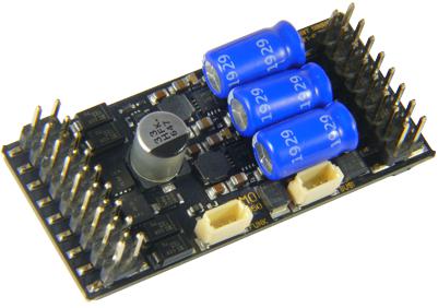
MS950 |
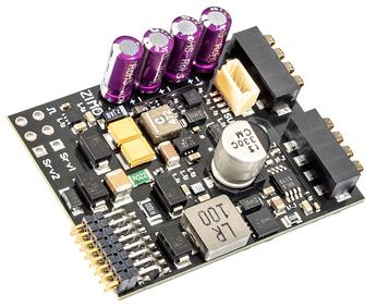
MS920LE |
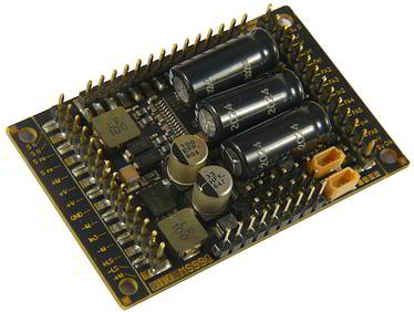
MS990L |
MS990K |
| |
|
|
|
|
|
| |
Matching locomotive and adapter boards
in set |
LOKPL950K | LOKPL950P | ADAUS950 MS950K MS950P MS970 |
⸺ |
LOKPL990P
(included in delivery) |
⸺ |

|
Dimensions (mm) |
50 x 23 x 13 |
38.5 x 29.8 x 12 |
50 x 40 x 13 |
50 x 40 x 13 |
| |
The dimensions of decoders with standardized interfaces (PluX, MTC, NEM-651, Next18) correspond to the corresponding standards by VHDM and NMRA or are smaller. In case of the wired decoders, which are protected by a shrinking tube, the indicated dimensions are WITHOUT this tube, because it can be taken off, if there is not enough space.
|
|
|
|
ConnectionsWires and/or standardized interfaces |
34 pins |
16 pins / spring contacts
(solderless compatible with LENZ VT98) |
63 pins | 38 screw terminals +21 pins |
| |
MS950: 1 x 18-pin + 1 x 16-pin male header. Additionally, a second SUSI interface (SUSI-1) and a radio connector.
For connections on the locomotive circuit board, see the wiring diagrams. MS920LE: 1 x 16-pin header + 2 x 4 spring contacts. Fully pin-compatible (including roof spring contacts) with the original Lenz decoder installation without soldering.
For details, see wiring diagrams. MS990L: 3 x 14-pin header sockets; the outermost pins on the left and right header sockets were mainly added for a 2 x 14-pin Märklin interface and are otherwise rarely used (duplicated pins or second SUSI interface)
For connections on the locomotive circuit board, see wiring diagrams.
MS990K: 2 x 12-pin and 1 x 14-pin screw terminal strips (the outermost connections on the left and right sides are not used, see above).
For connections on the locomotive circuit board, see wiring diagrams
|
|
|
|
Total current (continuous):
motor+sound+FOs(peak) |
4 A(10 A) |
1.8 A(2.5 A) |
6 A(10 A) |
6 A(10 A) |
|
Total current means motor current plus current of the function outputs plus consumption of the sound generators. Usually, the current used by the consumers on the function outputs is very low (only a few LEDs), as is the current consumption for the sound production (as average over time) also, so that the total current usually is available for the motor output. Therefore, the total current and the motor current are usually indicated with the same value. In case a function output has a higher continuous load (e.g. because it has a smoke generator connected) the motor output provides less current.
NOTE: The continuous load is against common interpretation not limited by the motor amplifier, but by the heat development on the PCB. Therefore: the smaller the decoder the less current flows, especially less total current.
|
|
|
|
Motor current (continuous)(peak) |
4 A(10 A) |
1.8 A(2.5 A) |
6 A(10 A) |
6 A(10 A) |
Continuous Current |
The continuous current indicates the possible continuous load at normal conditions (normal room climate and circulating air in the room where it is used). At about 100°C (212 F) on the PCB, the temperature sensor shuts down the consumers (in contrast to exceeding the peak current, at which the current sensor reacts).
At overload or overtemperature, the headlights start flashing at fast pace (about 5 Hz = 5 times per second). As soon as the PCB cooled down for 20°C (hysteresis), the motor is turned on again automatically.
The actual resilience of the motor is influenced by various factors, e.g. the track voltage (the higher, the more heat loss and the lower the possible continuous current), type and condition of the motor (low-ohm, etc. ) Dirt and heat from the outside are not helpful either.
ZIMO decoders can be overloaded (50% - 100% up to the peak current) for a short period of time. Usually, the peak current can be endured about 20-30 seconds, but only if the decoder was not at its limits beforehand. Currents in the medium area are naturally fine for a longer time, usually for a few minutes. This way, the usual hills on a model railway layout can be overcome, on the way down the hill the decoder cools down again. |
Peak Current |
While the continuous current refers to a long-time heat development of the decoder, the peak current indicates the threshold on which the current consumption (even with hypothetically perfect cooling) reaches the maximum of resilience of the motor amplifier. After reaching this threshold, it takes a few seconds or milliseconds until the decoder is shut down permanently. The fastest possible shut-down is reaching the threshold via a short circuit (depending on the type of decoder between 4 A and 10 A). ZIMO decoders possess an intelligent system, which prevents unnecessary shut-down but still is secure.
In case of a motor shut-down due to exceeding the peak current or because of a short circuit, the decoder is switched on again after about 3 seconds, but in this state it does not show any signs, like when shutting-down because of over temperature. |
|
|
|
Current on Function OutputsTotal of the FOs |
2 A |
1.8 A |
2 A |
2 A |
| |
The output current on a function output is indicated as sum (of all FOs or groups). A single output is, nevertheless, strong enough to handle the total current alone.
In case of an overcurrent, the decoder is turned off immediately, but depending on the anount exceeding the limit within a few tenths of seconds or milliseconds. This makes the cold start of light bulbs possible (if this is not enough, this can be defined within the software as Soft Start). |
|
|
|
number and type
Function Outputs
incl. 2 x headlights(+ LL outputs) |
11all 11 on plug
(+3 logic-level)
|
9on spring contacts
and pins |
15all 15 on plug
|
15all 15 on plug
|
| |
There are different kinds of (function) outputs:
- normal function outputs, often also called amplified outputs, to which front lights, light bulbs, uncouplers, smoke generators etc. can be connected. Each of these open-collector outputs is connected to the negative pole of the consumer; the positive pole of the consumer is connected to:
- Either the common positive pole of the decoder (on wires: the blue one)
- Or to a low-voltage output of the decoder if it has one,
- Or to an external power supply (e.g. a voltage regulator which is directly supplied by the tracks)
- Or (if there is no positive pole accessible, often at miniature decoders with NEM-651 interface) to one of the track poles (has the effect of reduced brightness of lights)
- Logic-level outputs (unamplified) are outputs, which supply a voltage level (5 V / 0 V) depending on if they are switched on or off. They are supplied via an internal protective resistor (usually 10 kOhm, i.e, a maximum of 0.5 mA current). Those outputs can be used:
- Either with the help of an external amplifier, either self-made or with the ZIMO product M4000Z
- Or as servo control wires (the traditional servos are compatible with the logic-level outputs)
- Or as control wires for SUSI interfaces, and for I²C busses.
The typical two logic level outputs, which almost every ZIMO decoder has, are switched between the possible applications by CVs.
By factory default these "SUSI pins" are set as SUSI Clock u. Data as follows: Logic Level CV #124 bit 7=0, Reed CV #393 bit 5=0, I²C CV #394 bit 2=0, and Servo Control Line CV = 0 (CV # see line 'Servo control wires").
If you want to switch to logic level outputs, set CV #124 bit 7 = 1 (value 128).
The function of the outputs is now defined and the CV values of the other possible modes listed above are ignored. If the logic level is inactive (bit 7 = 0), the next active value of the function modes in this order is valid.
- "LED outputs", special forms of logic level outputs, as in the MS580 decoder They supply a constant current of up to 6 mA, so that one LED can be connected directly (i.e. without series resistor!), which has to be connected to the positive pole of the decoder.
NOTE: The respective positive poles of the consumers connected to the function outputs can be connected to common positive, low voltage 5V, low voltage 10V, or to variable low voltage (adjustable by CV #264) as required.
|
|
| |
Low Voltage
5 V for Servos a.o. consumers
5 V resp. 10 V audio voltage
variable low voltage from 1,5 V
|
1.5 A
0.5 A
5 V do not overload!
not available
|
+12 V output on spring contacts
|
1.5 A
0.5 A
2 A
10 V do not overload!
|
1.5 A
0.5 A
2 A
10 V do not overload!
|
| |
Most MS-Sound decoders have a 5 V low-voltage source, which is used to operate LEDs, for example. This means that less energy is "burned up" than if the LEDs were operated at full voltage via a 1.5 kO resistor, for example, and in addition, fluctuations in the track voltage are kept away from the lighting, i.e. the brightness fluctuations are avoided.
|
|
|
|
Servo control wires
(complete witch 5 V supply) |
2Servo wires
+2 alternate use
of logic-level |
2Servo wires
|
6full feat. 3-pole
servo connection
(YES) |
6full feat. 3-pole
servo connection
+2 alternate use
of SUSI pins |
| |
If the logic level outputs/SUSI pins are switched to servo control wires by means of CVs (see above, line "Number and type of function outputs"), commercially available servos (Graupner, Robbe, etc.) can be controlled, for which various operating modes, end positions and rotation times can be set.
A setting (CV value > 0) activates the function as servo control line (if logic level, reed and I²C are deactivated, see above).
Responsible CVs for most MS decoders are CVs #181, #182,
but
for MS950 #183, #184,
for MS990 page 145 #281, #282.
The 5 V supply for the servos has to be provided externally, as far as the decoder does not have a low-voltage output.
|
|
|
|
SUSI - connection
alternatively SUSI, I²C, sound loading |
yesindividual 4-pole
SUSI connection
|
yesindividual 4-pole
SUSI connection |
yesindiv. 4-pol.
SUSI conn.
|
yesindividual 4-pole
SUSI connection
|
| |
By default, the SUSI signal (SUSI Data, SUSI Clock) is present at the logic level outputs (see line "Function Outputs") because bit 7 of CV#124 is not set (binary 0). By setting bit 7 of CV#124 to binary 1, the SUSI signal present there is deactivated and you can use the two pins as switchable logic level outputs if CV#181, CV#182 = 0 at the same time, because otherwise a servo control signal is present at these two pins.
The SUSI interface is used in vehicles with partly upgraded interfaces for data transmission, where electronics are integrated, i.e. panto drives, smoke generators, uncouplers, etc. The original idea of the SUSI interface, namely controlling external sound modules, has moved to the background, because sound decoders provide better solutions and in contrast to the past can be manufactured with smaller dimensions.
The SUSI pins of the ZIMO sound decoders used to load sound projects fast and efficient (2 minutes instead of 10 via tracks) has nothing to do with the original protocol and thus does not haveto be configured. Switching to this operating mode is done automatically before starting to load the sound project via the sound loading device MXULFA or a correspondingly developed ZIMO command station. |
|
|
|
Switch Inputs
for cam sensors, Reed switches, i.a. |
4 on pin connector
+2 alternate use of logic-level |
— |
4 on pin connector
+2 alternate use of logic-level |
4 on screw terminal
+2 alternate use of logic-level |
| |
Switch inputs are used to connect cam sensors directly (to play back chuff sounds synchronously to the axles) or sensors for position dependent sound functions, e.g. warning whistles before a level crossing.
Note: The logic-level outputs (see above) can also be used as switch inputs, if needed and the software supports functions with switch inputs (e.g. position dependent lighting effects or loco controlled commuting. This is also valid for non-sound decoders.
|
|
|
|
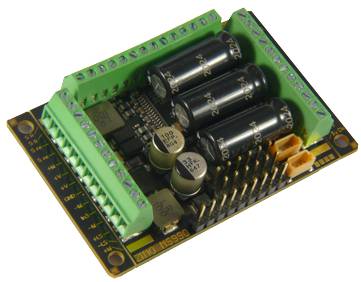
Energy Storage connection
16 V - capacitors DIRECTLY to the decoder |
internal:
3 Supercaps
yes
external on pins/screw terminal |
internal energy storage
4 Goldcaps
yes
|
internal:
3 Supercaps
yes
external on pins terminal |
internal:
3 Supercaps
yes
external on pins terminal |
| |
A stay-alive capacitor connected to the decoder in the form of Elkos (electrolytic capacitors), Tantals (Tantal capacitors) or Supercaps (old denomination: Goldcaps) takes over the supply of the decoder and connected consumers during interruptions of the wheel-track-connection due to dirt, insulated frogs or similar. Starting with a capacity of about 200 µF a positive effect can be seen; at least 1000 µF are recommended.
Additionally to preventing getting stuck, flickering lights and interruptions of the sound, a capacitor also reduces heating up the decoder (by reducing blind consumption) as well as motor sounds (limited by bridging the supply gaps by RailCom or HLU).
The MS large-scale decoders already feature an internal power supply with 3 supercapacitors (MS920LE 4 Goldcaps), which are normally sufficient. However, they also offer an external power supply connection for electrolytic capacitors, tantalum capacitors or supercapacitors meaning no additional components are required. The internal circuitry ensures optimal (standard-compliant current-limited) charging and discharging of the energy storage unit and is included in the price of the decoder, unlike power packs and similar accessories required for non-ZIMO decoders. Furthermore, a voltage rating of 15 V is sufficient for connected electrolytic capacitors or supercapacitors, even if the operating voltage is higher (tantalum capacitors should have a voltage reserve due to their design, i.e. at least 20 V). MS decoders (unlike ZIMO MX decoders) place NO limit on capacitance, but more than 1 farad is of little practical use.
The decoders MS480 and MS490 have a simple charge and discharge circuit, which is why only an energy storage device with low capacity can be connected to them (max. 1000µF). For the energy storage connection Elkos and Tantals with a resilience of at least 16V are sufficient, even if the driving voltage is higher. The MS580 has a charge and discharge circuit for capacitors with a resilience of at least 5 V, to which, among other things, 6.3V Tantals can be connected.
|
|
|
|
Speaker Outputs
dep. on dec. 8 Ω or 4 Ω
(2 x 8 Ω in parallel) |
2 x
3 Watt / 4 - 8 O
on solder pads |
1 x
3 Watt / 4 - 8 Ω
on pins |
2 x
10 Watt / 4 - 8 O
on pins |
2 x
10 Watt / 4 - 8 O
on terminals |
| |
The speaker outputs on MS large-scale decoders can be connected to either 8-ohm or 4-ohm speakers. These outputs operate at a voltage of 10 V (unlike H0 and miniature decoders, which use 5 V), which is what makes an output of up to 10 W at 4 ohms possible in the first place. Large-scale decoders also have two independent speaker outputs, which can be utilised in appropriately designed sound projects, for example to make the bell sound from a different position to that of the motor, or to acoustically separate the two motors of a vehicle.
A general exception here is the MS920LE, which is based on the MS450 and therefore has a single 5V audio output.
When choosing a speaker, the rule is: the bigger, the better. But of course, sound quality also depends on professional installation (resonance chamber or airtight locomotive body as a resonance chamber, openings in the body, etc.)
You will also find a wide selection of speakers for MS decoders in the ZIMO range.
|
|
|
Sound Flash |
128 Mbit |
128 Mbit |
128 Mbit |
128 Mbit |
| |
MS decoders possess a sound flash of 128 Mbit and possible frequencies of 22 and 44 kHz. (22 kHz are standard, what provides playback time of 360 seconds (with 16 bits).
|
|


 collapse all
(useful to print out the complete information)
collapse all
(useful to print out the complete information)